
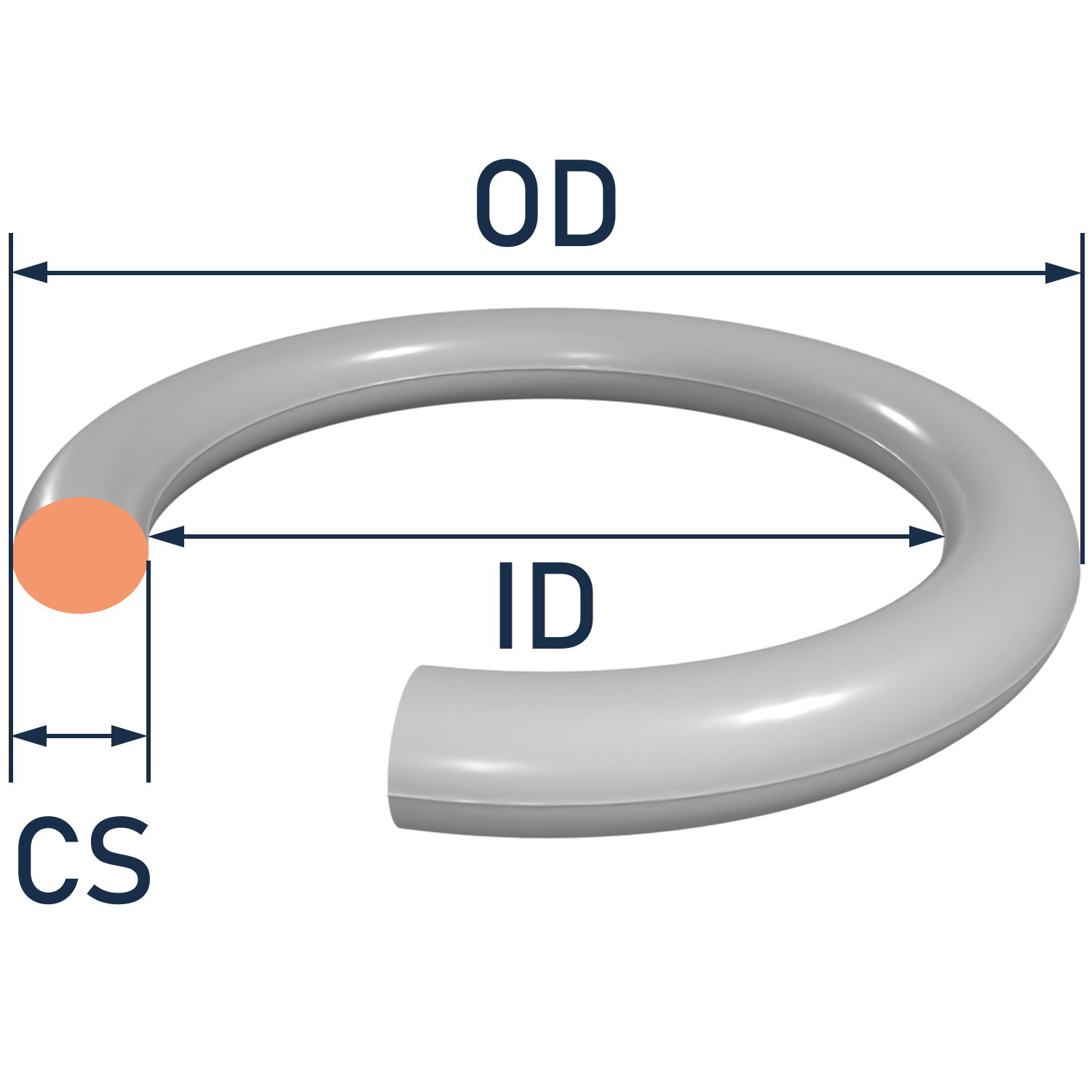
Rod (Dynamic Rotary) Design Guide
'Rod' styled O-ring grooves are commonly used dynamic rotary O-ring sealing configurations. This page specifically concerns dynamic (moving) rotary Rod O-ring seals.
The purpose of the tables below are to serve as a design guide for dynamic rotary Rod O-ring grooves using AS568 O-ring sizes+.
Please see our General Groove Guide for more information, or feel free to get in touch with our engineers if you have any questions.
*Feet per minute = 0.26 X Shaft Diameter (inches) X rpm
**Total indicator reading between groove OD, shaft, and adjacent bearing surface
*** If clearance (extrusion gap) must be reduced for higher pressures, bearing length M must be no less than the minimum figures given. Clearances given are based on the use of 80 shore durometer minimum O-ring for 55.2 Bar (800 psi) max. See Figure 3-2 for recommended clearances when pressures exceed 55.2 Bar (800 psi).
**** The use of O-rings as high speed rotary shaft seals is usually not recommended for applications requiring lower than -40°C (-40°F) or higher than 121°C (250°F) operating temperatures.
***** The O-ring gland in a rotary shaft application should not be used as a bearing surface. The shaft should be contained by bearings that will permit the O-ring to operate under the lowest possible heat and load
+ Please note that some AS568-0XX O-rings have atypical cross sections. Please see our General Groove Guide for more information, or feel free to get in touch with our engineers if you have any questions about O-rings, gaskets, & custom molded parts.
Canyon Components O-ring dynamic rotary groove design guide with specifications for AS568, Kalrez®, Canrez®, Chemraz®, and Parker® O-rings in high-speed rotary sealing applications.

Surface Finishes are RMS Values
| DASH # RANGE | O-RING CROSS SECTION | MAX ROTATIONAL SPEED * | GLAND DEPTH (D) | SQUEEZE | GLAND WIDTH (W) | CLEARANCE *** (H) | MAX ECCENTRICITY ** | BEARING LENGTH MIN *** (Z) | GLAND CORNER RADIUS | |||||||
|---|---|---|---|---|---|---|---|---|---|---|---|---|---|---|---|---|
| AS568 | Nominal (in) | Feet Per Min (FPM) | Nominal (in) | Percent | Nominal (in) | Nominal (in) | Nominal (in) | Nominal (in) | R1 (in) | R2 (in) | ||||||
| -004 through -045 | 0.070 ± 0.003 | 200 - 1500 | 0.065 - 0.067 | 0 - 11 | 0.075 - 0.079 |
0.012 - 0.016 |
0.002 | 0.7 | 0.01 | 0.005 | ||||||
| -102 through -163 | 0.103 ± 0.003 | 200 - 600 | 0.097 - 0.099 | 1 - 8.5 | 0.108 - 0.112 |
0.012 - 0.016 |
0.002 | 1.03 | 0.01 | 0.005 | ||||||
| -201 through -258 | 0.139 ± 0.004 | 200 - 400 | 0.133 - 0.135 | 0 - 7 | 0.144 - 0.148 |
0.016 - 0.020 |
0.003 | 1.39 | 0.018 | 0.005 | ||||||
Dynamic Seal Form
.png)


Back to Reference Hub

Dynamic Seal Design Variables
When designing a dynamic seal, it's important to take all relevant applicational variables into account. We have listed the most important ones below for your reference.
Canyon Components strives to meet all customer service requests. Feel free to contact Canyon Components engineering and let our knowledgeable staff help you design the perfect part for your needs.
- Is this a new or existing application? If it's existing, is the current seal failing in application?
- What quantity would you like for us to quote?
- What is the expected yearly usage for this seal?
- What are the maximum and minimum temperatures that the seal will experience in use?
- What pressures will the seal experience in use?
- What chemicals and media will be making contact with the seal during use?
- Is the sealing assembly used in a dynamic or static application? If dynamic, what type? (Rotary, translational, or both)
- If dynamic, what is the speed of movement or rotation?
- What groove type is the seal being used in? (Rod, piston, or face)
- What are the relevant dimensions for the groove assembly?
- Groove Width (W)
- Groove ID (A)
- Groove OD (B)
- Groove Depth (C)