
Dovetail O-Ring Groove Design Guide
Groove dimensions for dovetail grooves that hold the O-ring in place, by AS568 cross section
A dovetail groove is narrower at the top than at the bottom, so it holds the O-ring in place when the parts are separated. That makes it a good fit for lids, doors and valves that open often. The tables below give dovetail groove dimensions for every AS568 cross section.
'Dovetail' styled O-ring grooves are commonly used to hold an O-ring in place during assembly and maintenance. While Dovetail O-ring grooves are effective at keeping an O-ring in place, they are expensive to manufacture and should only be used if absolutely necessary.
The purpose of the tables below are to serve as a design guide for Dovetail O-ring grooves using all AS568 O-ring sizes*.
* Please note that some AS568-0XX O-rings have atypical cross sections. Please see our General Groove Guide for more information, or feel free to get in touch with our engineers if you have any questions relating to O-rings, gaskets, & custom molded parts.
For general guidance on compression, gland fill and stretch, see our O-Ring Groove Design Guide.
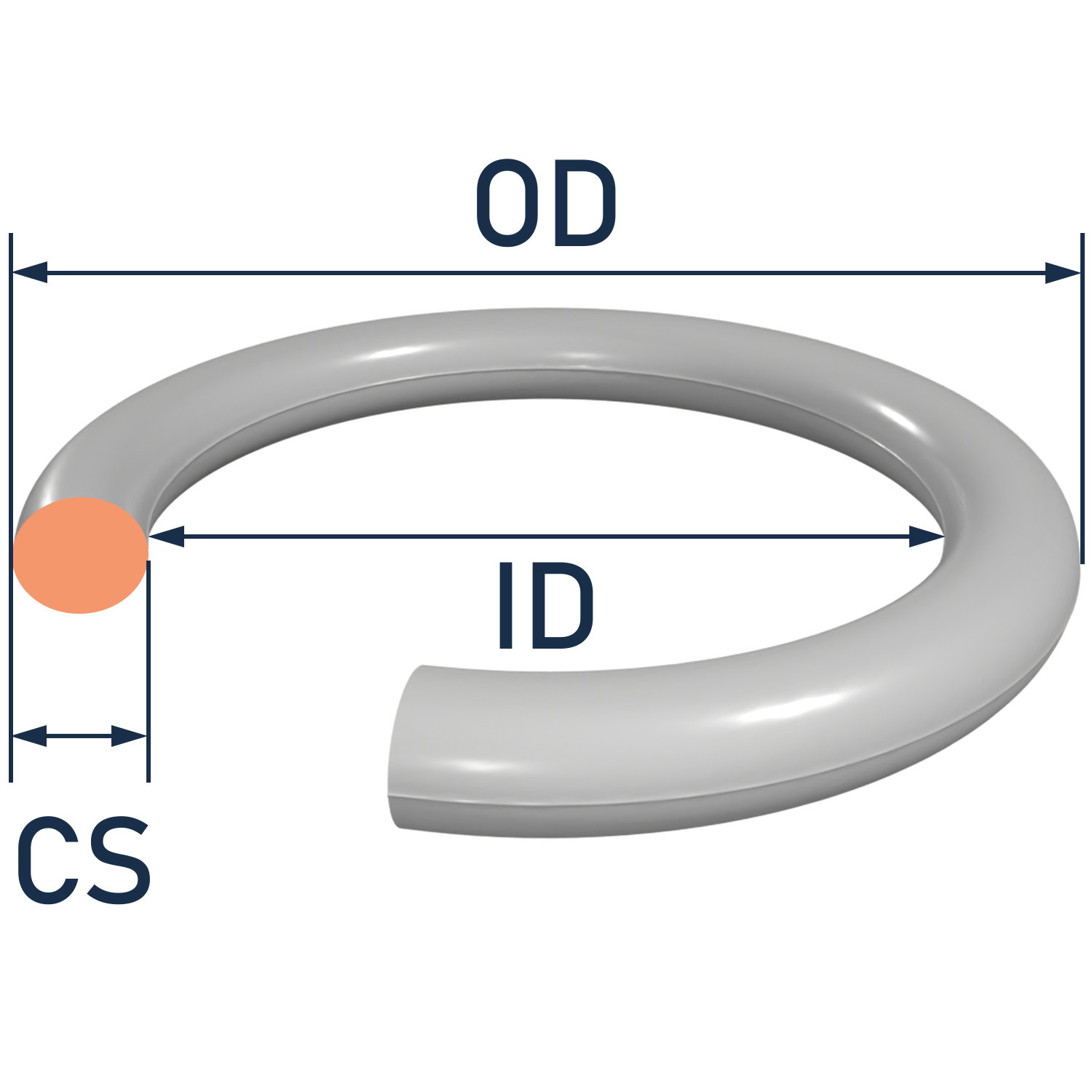
Canyon Components O-Ring Dovetail Groove Design Guide with specifications for dimensions, tolerances, and installation for Kalrez®, Canrez®, Chemraz®, and Parker® O-rings.

Surface Finish X: 32 RMS for liquids, 16 RMS for vacuum and gases
| DASH # RANGE | O-RING CROSS SECTION | GLAND DEPTH (D) | SQUEEZE | TOP CORNER GLAND WIDTH (W) | GLAND CORNER RADIUS | ||||||
|---|---|---|---|---|---|---|---|---|---|---|---|
| AS568 | Nominal (in) | Nominal (in) | Percent | Nominal (in) | R1 (in) | R2 (in) | |||||
| -004 through -050 | 0.070 ± 0.003 | 0.053 - 0.055 | 23 | 0.057 - 0.061 | 0.016 | 0.005 | |||||
| -102 through -178 | 0.103 ± 0.003 | 0.081 - 0.083 | 21 | 0.083 - 0.087 | 0.016 | 0.01 | |||||
| -201 through -284 | 0.139 ± 0.004 | 0.111 - 0.113 | 20 | 0.113 - 0.117 | 0.031 | 0.01 | |||||
| -309 through -395 | 0.210 ± 0.005 | 0.171 - 0.173 | 18 | 0.171 - 0.175 | 0.031 | 0.015 | |||||
| -425 through -475 | 0.275 ± 0.006 | 0.231 - 0.234 | 16 | 0.231 - 0.235 | 0.063 | 0.015 | |||||
O-ring Groove Design Tables

General O-ring Groove Design Guide
The O-ring general groove design guide is a comprehensive reference for engineers and designers. It offers versatile guidelines and recommendations for creating grooves that accommodate O-ring seals in various applications, ensuring effective sealing and preventing leaks.

Face Seal Groove Design Guide
The O-ring face seal groove design guide is an essential resource for engineers. It offers detailed instructions and best practices for designing grooves that accommodate O-ring face seals, ensuring effective sealing in hydraulic and pneumatic systems, reducing the risk of leaks and system failures.

Dove Tail Seal Groove Design Guide
The O-ring dovetail seal groove design guide is a comprehensive resource for engineers. It provides insights and recommendations for creating secure and precise dovetail grooves to accommodate O-ring seals, ensuring reliable sealing performance in critical applications.

Static Piston & Rod Seal Groove Design Guide
The O-ring static rod and piston seal groove design guide is an essential tool for engineers. It offers expert guidance on designing grooves for O-ring seals in static applications, ensuring effective sealing and preventing leaks in hydraulic and pneumatic systems.

Dynamic Piston & Rod Seal Groove Design Guide
The O-ring dynamic rod and piston seal groove design guide is an essential tool for engineers. It offers expert guidance on designing grooves for O-ring seals in dynamic applications, ensuring effective sealing and preventing leaks in hydraulic and pneumatic systems.

Dynamic Rotary Seal Groove Design Guide
The O-ring dynamic rotary seal groove design guide is a useful resource for engineers. It provides detailed instructions for creating grooves to accommodate O-ring seals in dynamic rotary applications, ensuring efficient sealing and minimizing wear in rotating equipment.
Back to Reference Hub